Active Window
Smart Building Automation System with CAN Bus Communication
Project Impact & Significance
Climate Challenge
Global electricity consumption per capita rose 2.6x from 1971-2014 (1,200 to 3,132 kWh), with 89.6% from non-renewable sources. Building automation can significantly reduce operational costs and carbon emissions through improved energy efficiency.
Market Problem
Current solutions are manufacturer-specific and expensive (Honeywell, Siemens), or use unreliable wireless communication with monthly subscription fees. Limited adoption due to high costs and proprietary lock-in.
Our Solution
Open-source, low-cost system using reliable wired CAN bus communication. Designed for widespread adoption to create non-negligible impact on residential greenhouse gas emissions through affordable smart building automation.
Project Overview
Problem Statement
Building automation systems can help reduce operational costs and carbon emissions by improving energy efficiency. However, many current solutions are manufacturer specific and expensive, making widespread adoption difficult.
Our Solution
Our project aims to assist the non-profit Manhattan-2 company develop "electrical and communications standards that define how devices interconnect within the building of the future."
- •Facilitate the development of an open-source software framework (Building Bus) to enable easy smart home device development
- •Develop a new CAN transceiver circuit that emphasizes smart building network priorities, particularly higher-reliability and lower operational power

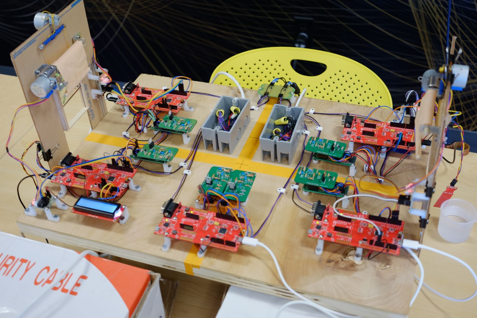
Active Window project team with prototype setup
System Specifications
Networking Software
- ✓Supports communication from master controller to devices
- ✓Support various function calls and commands
- ✓Supports tree networking topology
- ✓Processor sleeps when not processing network packets
- ✓Identify each device with serial number/address
- ✓Uses CAN bus communication protocol
- ✓Uses only C/C++
Physical Layer
- ✓Provides a maximum of 5mA of power to device transmitters
- ✓Defines a logic 1 and logic 0
- ✓Supports CAN bus (Wire-AND)
- ✓No damage to devices in event of accidental short
System Architecture & Implementation
Distributed Network Design
The prototype demonstrates a dual-network architecture with five XMC4200 boards. The system is divided into left and right networks, each powered by 16V and housed in electrical boxes for safety and organization.
A central repeater board with dual PCB transceivers enables message forwarding between networks, creating seamless communication across the entire system while maintaining network isolation for fault tolerance.
Smart Sensor Integration
Three sensor types provide comprehensive environmental monitoring: TMP36 temperature sensors(calibrated against reference thermometer), photoresistors for light detection, and water level sensors for rain detection.
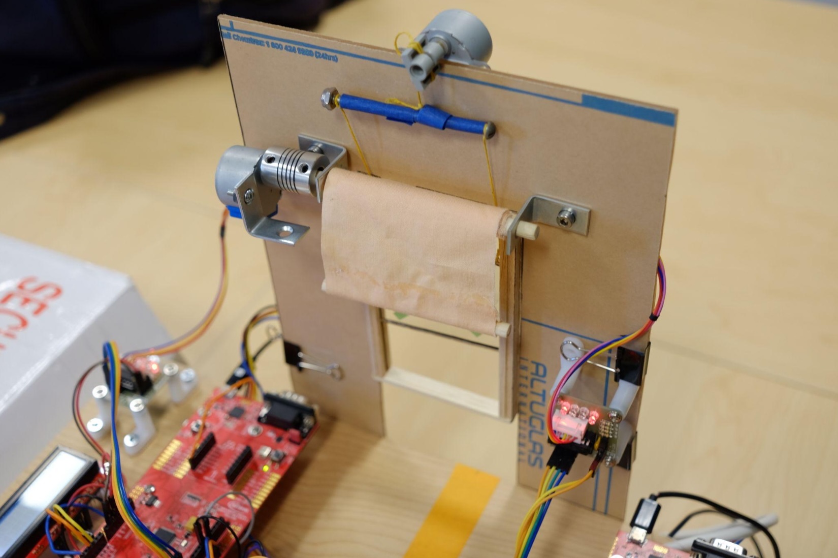
28BYJ-48 stepper motors with ULN2003 drivers provide precise window and blind control with excellent holding torque for safety. Custom-built 6"x4" balsa wood windows with plexiglass and cloth blinds demonstrate real-world applications.
Interrupt-Driven Real-Time System
The software architecture uses interrupt-driven programming for optimal performance. Timer interrupts fire every 10ms for sensor readings, while network interrupts handle incoming CAN messages. This approach minimizes CPU overhead and ensures responsive system behavior across all distributed nodes.
Live System Demonstration
System Demo Video
Watch the complete Active Window system in action, demonstrating automated window control, sensor integration, and CAN bus communication between XMC4200 boards.
Technical Achievements & Performance
Requirements Achievement Status
Fully Achieved
- ✅ Logic Definition - Clear logic 1 and 0 states
- ✅ CAN Bus Support - Hardware-accelerated communication
- ✅ Tree Topology - Flexible network architecture
- ✅ Broadcast Messaging - Network-wide communication
- ✅ Reliability - Zero dropped packets achieved
Partially Met
- ⚠️ Power Consumption - <5mA target limited by dev board overhead
- ⚠️ Point-to-Point Messaging - Broadcast implemented, P2P pending
Technical Design & Implementation
Physical Implementation

Prototype Setup
Complete prototype setup with XMC4200 boards and sensors

Window Assembly
Motorized window assembly demonstrating automated control system
System Architecture

System Diagram
Overall system architecture showing component interactions and data flow

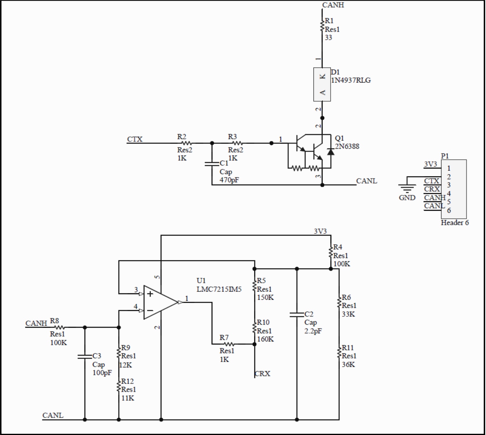
CAN Transceiver Circuit
Custom CAN transceiver circuit design for smart building networks
PCB Design & Hardware

PCB Schematic Design
Custom PCB Schematic optimized for CAN bus communication and power efficiency

PCB Layout Design
Custom PCB layout optimized for CAN bus communication and power efficiency
Performance Testing & Hardware Specifications
Frequency Analysis & Response Testing
Network Performance Metrics
- Message Transmission Range:1000+ feet
- Network Response Time:10ms average
- Packet Loss Rate:0%
- Bus Voltage:16V stable
Sensor Calibration Results
- Temperature Accuracy:±1°C (calibrated)
- Light Sensor Range:0-1024 ADC values
- Stepper Motor Precision:2048 steps/revolution
- System Update Frequency:100Hz (10ms interrupts)
Custom PCB Design & Implementation
Developed a custom PCB design that serves as the foundation for our distributed network architecture. The board features an integrated CAN transceiver, power regulation circuitry, and standardized sensor/actuator interfaces.
Key Components
- • XMC4200 microcontroller
- • MCP2551 CAN transceiver
- • LM7805 voltage regulator
- • Status LED indicators
- • Screw terminal blocks
Design Features
- • Isolated power domains
- • ESD protection circuits
- • Modular sensor interfaces
- • Debug header access
- • Compact form factor
Technical Specs
Our Creative Team
UMass Senior Design Project Team 15

Michael Chan
CAN Protocol & Power Systems Engineer
EE
CAN protocol implementation, power distribution analysis, requirements validation, component sourcing

Dingbang Chen
Firmware & Mechanical Integration Engineer
CompE
Firmware development, stepper motor integration, mechanical calibration

Nathan Johnson
Network Architecture & Software Engineer
CompE
Network topology design, interrupt handling, firmware development, performance testing

Tien Shen
Sensor Engineer & Project Coordinator
CompE
Sensor integration & algorithms, PCB design, window assembly fabrication, team coordination
Collaborative Achievement Highlights
Hardware Excellence
- • Custom PCB design from concept to manufacturing
- • Robust power distribution with 16V bus system
- • Modular sensor interfaces for scalability
- • Professional-grade component selection and sourcing
Software Innovation
- • Real-time interrupt-driven architecture
- • Reliable CAN bus protocol implementation
- • Advanced sensor calibration algorithms
- • Zero packet loss network performance